PCB Capacitors are one of the most commonly used PCB components on circuit boards, and they play various critical roles such as coupling, decoupling, bypassing, filtering, timing circuits, and energy storage. Choosing the ideal circuit board capacitor is crucial to ensure your circuit board performs reliably and efficiently. In this blog, we will be covering how PCB board capacitors work, their key functions, and the different types. By the end, you’ll know exactly what important aspects to consider when selecting the ideal capacitor for your design. Ready to learn about this useful component? Let’s get started!
What Are PCB Capacitors? How Do They Work?

PCB capacitors are passive electronic components mounted on circuit boards that store and release electrical energy. They store charge physically rather than chemically. Capacitors are made up of two conductive plates that are separated by a dielectric material (ceramic, polymer, or electrolyte). Once the voltage is applied, the capacitor’s two plates acquire positive and negative charges respectively. Due to the difference in charge, an electric field is generated across the dielectric. As a result, the function of the dielectric material in between is to prevent these oppositely charged particles from bonding together. When the PCB needs this charge, the PCB capacitor releases energy to meet the requirements of the circuit.
4 Key Factors Influencing Capacitance
The capacitance (C) of a PCB capacitor is mainly affected by these four factors: plate area, plate overlap, plate distance, and dielectric. Here is the general equation to show how they relate.

| Factors | Mathematical Relation | Impact on Capacitance |
| Plate Area (A) | C ∝ A | The capacitance value rises as the plate area does. |
| Plate Overlap | C ∝ Overlap % | The capacitance value rises with an increase in the parallel plates’ overlap area. |
| Plate Distance (d) | C ∝ 1/d | The closer the distance between the parallel plates, the higher the capacitance value. |
| Dielectric (ε) | C ∝ ε | Selecting a dielectric material with a high dielectric constant will also increase the capacitance value. |
What Are the Critical Functions of PCB Board Capacitors?
PCB capacitors offer various important functions, making them critical to ensure smooth and reliable circuit board operation. Let’s dive into their detailed roles to understand why they matter.
Coupling
Coupling capacitors can transfer signals from one circuit stage to another while blocking the flow of DC signals and allowing AC signals to pass. Because in many applications such as audio and RF circuits, we only need AC signals but do not want DC signals to affect signal transmission.
Decoupling
When an integrated circuit (IC) quickly starts or stops working, current demand may suddenly increase or decrease, causing a momentary voltage sag or voltage spike. Decoupling capacitors can provide backup power to components during temporary current demands and prevent voltage sags from affecting circuit performance.
Bypassing
A bypass capacitor is also a type of decoupling capacitor. Its purpose is to filter away high-frequency noise by giving it a low-impedance path to the ground. Bypass capacitors can also help regulate voltage to remain stable when loads fluctuate, avoiding circuit failures.
Filtering
Filter capacitors can eliminate unwanted noise and interference, selectively allowing or blocking certain frequencies of signals to pass through, ensuring accurate and clean signal transmission. PCB capacitors are also used as filters in power circuits, whose function is to smooth voltage fluctuations, commonly used to filter out AC ripples.
Timing Circuits
The PCB capacitors are essential for timing circuits. By charging and discharging at a controlled rate, capacitors and resistors/inductors can control the duration and frequency of signals. In clock and timer applications, this is particularly crucial.
Energy Storage
A final role of PCB capacitors is to quickly store electrical energy and release it when the board needs it. This helps maintain a steady flow of current in the circuit and ensures smooth operation.
5 Types of Circuit Board Capacitors
Now that you have a basic understanding of PCB capacitors, we look deeper into five types of capacitors commonly used in circuit board designs.
Ceramic Capacitors
Ceramic capacitors utilize ceramic materials (barium titanate or titanium dioxide) as the dielectric, which is a good insulator. They are small, affordable, and perform well in high-frequency applications, making them ideal for decoupling, noise suppression, and filtering.
Electrolytic Capacitors

Electrolytic capacitors look like small tin cans, are larger than other types of PCB capacitors, and offer larger capacitance values. Their dielectric is a very thin layer of insulating oxide that is etched onto an anode foil made of tantalum or aluminum. More importantly, this is a polarized capacitor that needs to be connected correctly according to its polarity characteristics to work. Otherwise, it may cause damage or explosion. Electrolytic capacitors are often used in buffering, smoothing, and bulk decoupling applications that require large capacitance values.
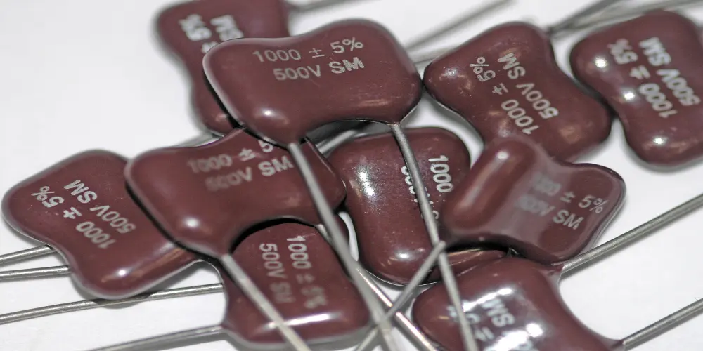
Film Capacitors
Film capacitors employ a thin plastic film like polypropylene or polyester as the dielectric and are available in both leaded and SMT packages. They are versatile and cost-effective for coupling and frequency filtering applications.
Mica Capacitors
Mica capacitors use mica sheets as dielectrics and silver or metal deposited on mica as electrodes, with good stability and low loss. This type of capacitor is often used in applications such as signal coupling, tuning, and bypass in high-frequency circuits.
Supercapacitors (Ultra-Capacitors)
Supercapacitors utilize electrolytes and porous electrode materials to achieve ultra-high capacitance (up to thousands of farads) while having a compact size. They excel in repeated charge/discharge cycles and energy storage applications.
To help you better understand the five capacitor types, we’ve compiled a detailed table below.
| Aspect | Ceramic Capacitors | Electrolytic Capacitors | Film Capacitors | Mica Capacitors | Supercapacitors |
| Dielectric Material | Ceramic materials | Thin oxide layer | Thin plastic film | Mica sheets | Porous electrode materials and electrolytes |
| Dielectric Permittivity | Low to high | Medium | Medium | Medium | Not applicable |
| Working Voltage | Up to 100 kV | 2V up to 600V | 50V to 2kV | 50V to 7kV | 2.3V to 5.5V |
| Capacitance Range | 1 pF to 100 μF | 1 μF to 1 F | 1 nF to 30 μF | 1 pF to 0.01 μF | Up to thousands of farads |
| Tolerances Rating | ±1% to ±20% | ±20% | ±1% to ±20% | ±1% to ±5% | -20% to +80% |
| Operate Temperature | -55°C to 200°C | -55°C to 125°C | -55°C to 125°C | -55°C to 125°C | Broad range |
| Leakage Current | Very low | Moderate to high | Very low | Very low | Moderate to high |
| ESR | Extremely low | High | Low | Very low | Ultra-low |
How to Choose the Right PCB Capacitors for Your Board?
Once you’re familiar with the 5 main types of PCB capacitors, you might be wondering, how do I select the best capacitors for my design? To make the right decision, here are the key factors you need to consider carefully.
Capacitance Value
The capacitance directly determines the capacitors’ ability to store and release charges. The minimum required capacitance value needs to be calculated based on the circuit’s operating principle and performance requirements. And the capacitance of the capacitor needs to meet the minimum requirements of the board with a safety margin of more than 20%.
Dielectric Permittivity
Different dielectric materials provide varying degrees of insulation performance. As explained earlier, the dielectric constant is one of the most important parameters in affecting capacitor performance, and its value will be directly proportional to the capacitance value. That is, the higher the dielectric constant, the higher the value of capacitance will be.
Voltage Rating
The highest voltage that PCB capacitors can safely tolerate for an extended period of operation is called the rated voltage. To ensure the reliability and longevity of capacitors, their rated voltage should be at least 50% greater than the maximum voltage of the circuit. A margin like this can safely avoid over-voltage dangers caused by voltage fluctuation, transient spikes, or ambient temperature changes, and thereby prevent dielectric breakdown and capacitor failure.
Tolerance
Capacitor tolerance refers to the minimum and maximum allowable deviation range between the actual capacitance value and the nominal value of a capacitor. This tolerance can affect the electrical performance of PCBs, especially in sensitive applications such as signal processing, filtering, or high-frequency circuits.
Temperature Range
The capacitor temperature rating is the maximum ambient temperature that the capacitor can operate safely and reliably. This rating is critical because the capacitor must endure not only the heat generated by the PCB itself but also the operating ambient temperature. Operating above the rated temperature of the capacitor will result in decreased performance, shorter lifespan, and even failure.
Leakage Current
The capacitors experience slow loss of stored electric energy in a process called leakage current. For timer and energy storage applications, there is a need for low leakage capacitors to avoid leakage resulting in loss of energy and loss of timing accuracy, therefore system accuracy and reliability. In other applications where lower energy storage is needed, higher levels of leakage can be acceptable.
Equivalent Series Resistance (ESR)
Equivalent series resistance (ESR) is a key parameter for measuring the power loss and heating caused by the internal resistance of a capacitor, which directly affects its performance and efficiency. Low ESR capacitors, such as ceramic and film capacitors, perform well in high-frequency bypass, filtering, and decoupling applications. As they have the ability to minimize energy loss and heat dissipation issues with guaranteed stable performance at high-frequencies.
Last Thing
Understanding PCB capacitors is essential to designing reliable and efficient circuit boards. The five capacitor types that have been discussed each possess distinct different features and applications to meet various circuit requirements. When selecting capacitors, carefully consider key parameters to ensure optimal performance and long-term reliability of your PCB design. These critical parameters, along with thorough knowledge of capacitor types, enable engineers to make decisions to improve overall circuit performance.