The resistance of a 0 ohm resistor is nearly zero and hence gives practically no impedance. It serves several functions during circuit design that many have hardly ever imagined, offering flexibility and convenience to printed circuit board design. Common usages of 0 ohm resistors are shown in this blog to let you deeply know what function they will perform.
What Is a 0 Ohm Resistor?
A 0 ohm resistor, also known as a jumper resistor, is a special passive electronic component. Although its nominal resistance value is zero ohms, its resistance is actually close to 0, allowing the current to pass almost unimpeded. Zero ohm resistor is often used in circuits as a connecting jumper, replacing traditional solder jumpers or used as a placeholder in circuit design.
Two Main Types of Zero Ohm Resistors
There are two main types of 0 ohm resistors: Wire Wound 0 Ohm Resistor and Surface Mount 0 Ohm Resistor.

- Wire wound zero ohm resistors resemble conventional wire wound resistors in both appearance and construction. They typically feature a black marking band, which is one of their distinctive characteristics. This band clearly indicates their near-zero resistance and helps distinguish them from other standard resistors.
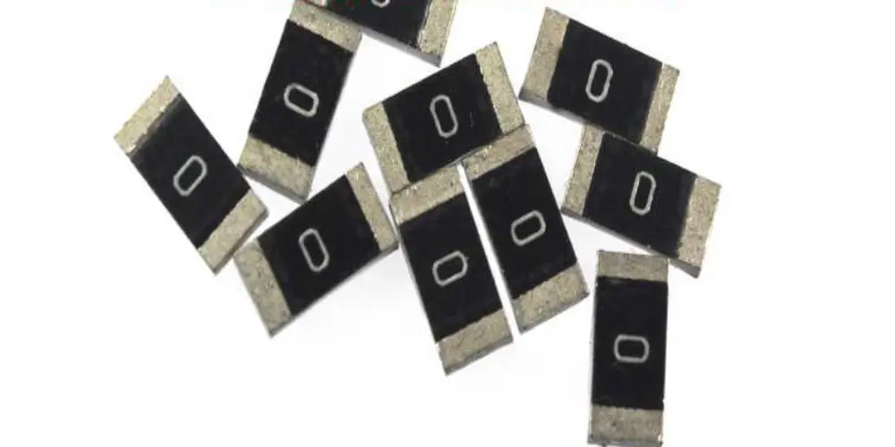
- The surface mount zero ohm resistor is a new type of resistor designed to replace traditional wire wound resistors. Compared to wire wound resistors, surface mount zero ohm resistors reduce costs, occupy less board space, and simplify both production and installation. Manufacturers typically mark the resistor’s surface with a single zero or triple zeros for identification.

Typical Uses of 0 Ohm Resistors
Quick Circuit Adjustments
A 0 Ohm Resistors can be used for debugging or compatible design on PCB. These resistors do not provide any actual electrical function in the circuit. They serve as placeholder components, jumpers, or connectors, enabling designers to quickly modify the circuit during the debugging and prototyping stages without the need for a circuit board redesign.
Jumper Alternative
It can be used as a jumper. If a part of the circuit doesn’t need to be connected, 0 ohm resistors can be used, offering both a neat appearance and ease of installation. Zero ohm resistors help minimize high-frequency interference that can be caused by traditional jumpers, which may act like antennas.
Bridging Routing Paths
In PCB design, when the circuit board area is limited and there are many traces, routing can become challenging. Zero ohm resistors provide an effective solution to this issue. They help designers bypass complex trace routing and act as bridges between two solder joints, establishing an electrical connection. This is particularly useful when single-layer PCBs cannot be drilled, as using zero ohm resistors can help reduce the production cost of multi-layer PCBs.
Power Consumption and Current Measurement
A 0 ohm resistor can be connected in series between the power supply and the load. After the prototype board is completed, designers can remove the 0 ohm resistor and measure the current directly with a multimeter at the soldering points. This allows them to calculate the actual power consumption of the chip or circuit. A 0 ohm resistor can be reserved in a specific circuit segment. By removing it and connecting an ammeter, designers can achieve accurate current monitoring, especially in high-current applications.
Overcurrent and Short Circuit Protection
Zero-ohm resistors have extremely low resistance and typically do not significantly limit circuit current. Although their current carrying capacity is limited, this characteristic provides a unique protective function. When a short circuit or overcurrent occurs, the zero-ohm resistor will quickly fuse, cutting off the current and preventing potential circuit damage and safety hazards.
Optimizing EMC Issues
In high-frequency signal circuits, the parasitic capacitance and inductance effects of 0 ohm resistors exist, but their impact is small and usually not enough to directly adjust the impedance matching of the signal like capacitors or inductors. As a connecting element, zero ohm resistors can indirectly help optimize EMC issues, especially in the circuit layout between ground connections or between power supplies and chip pins.
Securing Circuit Functions and Configurations
Zero ohm resistors can be used as an alternative to jumpers or DIP switches to change circuit functions or address settings. The 0 Ω resistors are soldered in the PCB that users cannot modify them. This helps protect the stability of the circuit and avoid unauthorized modifications.
Restoring Ground Plane Continuity
If the ground plane is split, the shortest path of return for the signal is disrupted, forcing the signal to make a detour. This creates a bigger area of the loop and increases electric and magnetic fields. Placing a zero-ohm resistor across the split restores the continuity of the ground plane and hence shortens the path of return, thereby reducing interference.
Connecting Digital and Analog Grounds
In mixed-signal circuits, digital ground and analog ground are usually separated to minimize current noise interference between the two. However, they still need to be connected at a single point to maintain circuit stability and integrity. Zero-ohm resistors provide a simple and effective way to connect these two ground networks while minimizing the risk of interference. During large-scale copper pours, zero-ohm resistors help prevent issues like floating ground and static electricity accumulation that can result from improper grounding. In similar scenarios, other solutions include using inductors, ferrite beads, or capacitors to address grounding issues.
Commonly Asked Questions on 0 Ω Resistor
QUESTION 1: What should be considered when using zero ohm resistors?
ANSWER 1: Zero ohm resistors have an extremely low resistance, which causes heat generation when current flows through them. Their current carrying capacity depends on the material and size, which determine their power rating. Designers must select the right zero-ohm resistors to ensure they can handle the expected current without overheating or damage.
QUESTION 2: How is a 0 ohm resistor different from a wire, and why choose it over a wire?
ANSWER 2: As mentioned above, zero-ohm resistors have many functions and can replace wires in certain applications. In large-scale PCB production, automatic placement machines can easily identify and place zero-ohm resistors and other components, while using jumper wires will add additional costs.
QUESTION 3: Do 0 ohm resistors vary in accuracy?
ANSWER 3: Yes, there is a difference. When the accuracy of zero ohm resistors is specified as ±1% or ±5%, there are many package styles. It includes common packages like 2512, 0402, 0603, 0805, 1206, 1210, 1812, etc. These different accuracy levels result in changes in the size and shape of the 0 ohm resistors.
QUESTION 4: What maximum current can flow through a 0 ohm resistor?
ANSWER 4: The real resistance of a usual 0 ohm resistor is 50 milliohms, with a deviation of about ±5%. Given that you know the rated power “P” and actual resistance “R” of a zero ohm resistor, you can calculate the maximum current “I” it can withstand. The formula goes like this: P=I2×R
Ending Notes
Generally speaking, 0 ohm resistors play a crucial role in today’s circuit design in terms of delivering low cost, high performance, and great versatility. Choosing the right zero ohm resistor can enhance the stability and performance of your circuit. For questions, feel free to contact UnityPCB, and we will be glad to assist you with any inquiry that you might have regarding 0 ohm resistor design.


