PCB soldering is one of the most basic processes in PCB assembly and PCB repair. Whether you’re a DIY enthusiast trying out a new electronic assembly or a professional working within the electronics manufacturing industry, you need to learn proper soldering techniques if you intend to build reliable electronic assemblies that will work for a long time. In this blog, we will explain how to do PCB soldering, different soldering techniques, and the required tools.
What Is PCB Soldering?
PCB soldering refers to a process of connecting electronic components to a printed circuit board (PCB) by using molten metal typically solder in order to make an electrical connection. When the molten solder cools and solidifies, a conductive joint is formed between the components and the PCB that provides a reliable electrical pathway for the circuit.
Different Types of PCB Soldering Techniques
- Soft Soldering
An ideal gentle process for delicate and intricate circuit board components with lower melting temperatures. Protecting fragile components requires the soldering temperature be kept under 400 degrees Celsius. This technique is commonly used for most electronic assembly work.
- Hard Soldering
With solid solder, it is a great technique to create stronger bonds between metal elements, especially for silver, gold, copper, or brass compositions. There are many subtypes, and silver soldering is one of the most well-known, using a silver alloy as a filler material to secure component attachment.
- Wave Soldering
It is an ideal automated process for both through-hole and surface-mount components. Here is how it works: PCB with components on it pass over a wave of molten solder, so as to create consistent joints across multiple connections simultaneously. This method is efficient for bulk assemblies.
- Reflow Soldering
This process is mainly used for surface mount technology (SMT) components. First, place the components onto pads that are covered with solder paste, then apply heat to melt the paste in order to create reliable electrical connections. This is a highly precise soldering method for modern electronic assemblies.
Recommended reading: Wave Soldering vs Reflow Soldering: Key Difference Revealed
Essential Soldering Tools and Equipment Needed
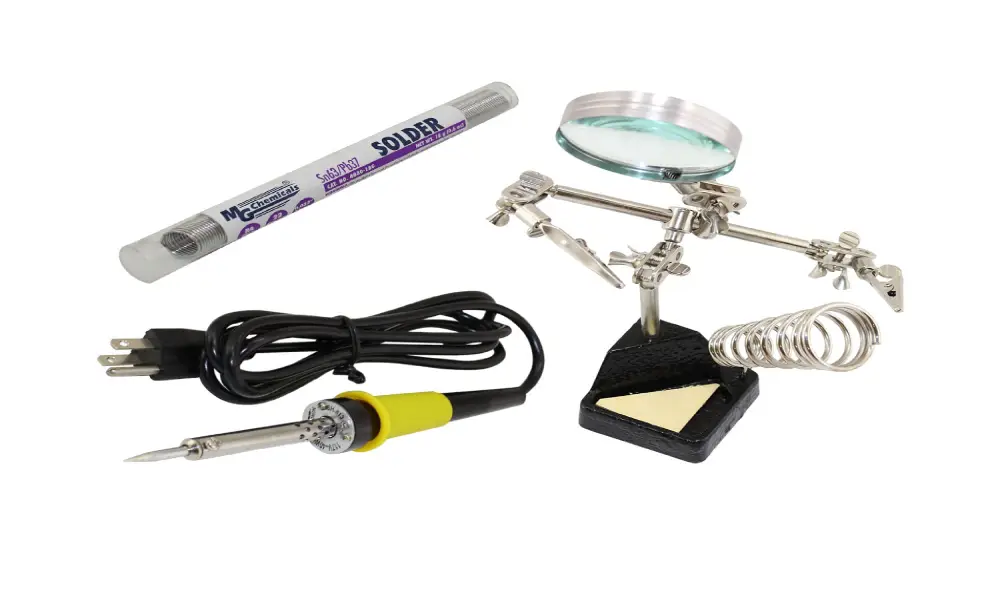
- Soldering Ironor Soldering Station
Any soldering work starts with a good quality soldering iron or station. Modern soldering stations have the feature of adjustable temperature settings and exchangeable tips, which accommodate different component sizes. Temperature control capabilities ensure the consistent heating time for creating reliable solder joints, and preventing damage to the components.
- Solder
Electronic soldering typically involves two main solder varieties: Lead-based and modern lead free compositions. Lead-based solder, though it has better workability and melts at lower temperature (about 180°C), is being replaced by lead free alternative for environmental and health reasons, though the latter require higher working temperature (about 220°C).
- Solder Flux
Solder flux actively removes oxidation from the metal surface, prevents further oxidation during the soldering process, and improves the flow characteristics of the solder. Flux is available in various forms, such as integrated flux-core solder wire, flux paste, or liquid flux.
- Desoldering Tools
Sometimes, you may need to remove or rework a solder joint. Desoldering tools are required, including desoldering pumps, desoldering braid, and soldering irons, which can be used to remove excess solder.
How to Solder a PCB: A Step-by-Step Guide
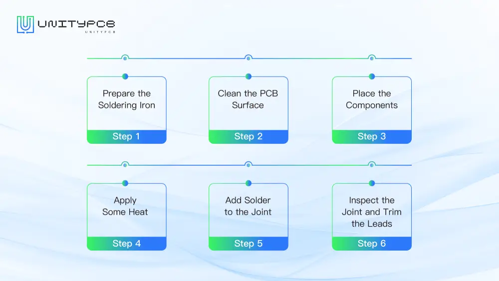
There are a few key steps involved in PCB soldering. I will provide you with a detailed, step by step guide to walk you through the process:
Step 1: Prepare the Soldering Iron
Preparing soldering iron is the first step in PCB soldering. First, you need to tin the tip (cover it with a thin layer of solder). Now heat the iron well, put enough solder on the tip to cover it completely. Once done this, wipe off any extra flux before it hardens. It’s important to check the temperature all the time. If you leave it on for too long, the high temperature of iron would damage the PCB.
Step 2: Clean the PCB Surface
Then, check the PCB surface is clean, with no dust, grease or dirt. Blow away any remaining bits of debris, using compressed air, then wipe the board down with an industrial cleaning pad. It is really important to clean the surface as the solder isn’t going to stick to a dirty surface and the connections won’t be reliable.
Step 3: Place the Components
When working with through hole parts, simply push the leads into the holes so that the part sits flat on the surface of the board. If you are dealing with surface mount components, place them on their pads at the right place; tweezers will be very handy for small ones. Make sure that polarized components such as capacitors and diodes are pointed the right way before soldering on.
Step 4: Apply Some Heat
Put the PCB onto a heat resistant pad to block it from moving during the process. Then put the soldering iron tip to the PCB pad and the component lead to apply heat. It will heat the two surfaces equally, which will ready the surfaces to receive solder flow. Keep the soldering iron in a place for just a few seconds to avoid overheating.
Step 5: Add Solder to the Joint
When heated, just touch the tip of some solder on the solder pad and the lead. By this time, the solder will flow on smoothly and the flux will begin to liquify. Add some more solder around the joint, forming a small mound. Then, set the soldering iron down and take it away from here.
Step 6: Inspect the Joint and Trim the Leads
When the joint has cooled, visually inspect the joint to see if it is smooth and solid. If everything looks OK, then trim any excess lead from the component just above the solder joint. If properly formed, we should have a small, clean cone shape on the joint.
Top 5 PCB Soldering Defects and How to Avoid
- Cold solder joints
If not heated properly, you’ll get a cold joint, characterized by a dull, grainy appearance (as opposed to smooth and shiny). Prevent this by keeping the soldering iron temperature in the range of 315-370°C and ensuring adequate heat contact time.
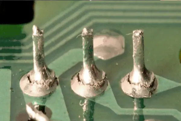
- Insufficient solder
If not enough solder is used, the joint won’t be properly covered and won’t deliver reliable electrical connections which can fail under stress. To avoid this issue, ensure complete coverage of the lead and pad areas, and it should form a proper fillet, so it resembles an hourglass shape.
- Solder Bridges
This defect refers to unwanted connections between adjacent pads or leads, which can cause short circuits and even device malfunction. Good control of the amount of solder and use of the appropriate sized iron tip can help to prevent solder bridges.
- Excess Solder
Using too much solder would waste materials; moreover, the oversized joints may hide bad joints underneath. To prevent this problem, just apply the solder amount needed and use solder wick to remove excess solder if necessary.
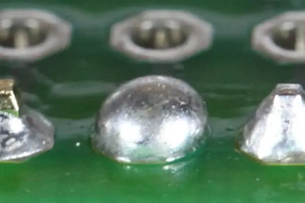
- Component Shift
This problem commonly occurs in surface mount devices. It is best solved by using the right PCB standoff, then securing the component with a single solder joint. Before proceeding, we have to wait for the joints to cool completely so as to prevent movement during assembly.
Conclusion
Soldering PCB is a skill that needs to practice, but it’s worth learning. From basic tools to different techniques like soft, hard, wave, and reflow soldering, we’ve covered it all. Don’t forget to watch out for common problems like cold joints and solder bridges; they aren’t inherently bad things, many people have these issues on their first attempts, but you’ll get better at spotting and preventing them.
At UnityPCB, we provide professional PCB assembly services that put these best practices to work. Whether you’re starting your first project or scaling up production, our experienced team ensures your PCBs are soldered right every time.
