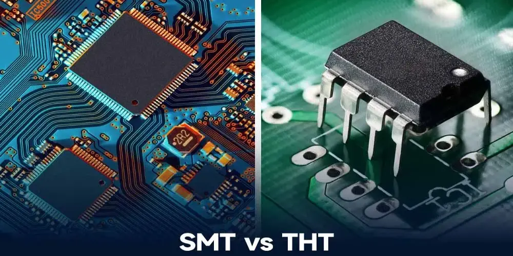
SMT vs THT are two common methods used in the PCB assembly process. Each assembly technology has advantages and disadvantages, and the choice you make will rely on the requirements of your project. In this blog, we will help you understand SMT vs THT, their core assembly process, the pros and cons, and key differences.
What Is SMT?
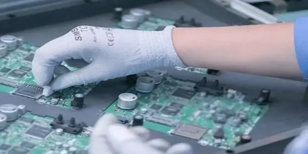
SMT (surface mount technology) is a widely used PCB assembly method. This technology directly solders components to precise areas on the surface of printed circuit boards without drilling holes. SMT is an automated method very well suited for volume manufacturing, enabling it to accelerate assembly speed as well as lower cost. Now, let’s explore the three key steps of SMT assembly process.
Three Key Steps of SMT Assembly Process
- Solder Paste Apply: Align and fix the PCB stencil on the circuit board, making sure that its opening matches the pad. Once you’ve aligned, put the solder paste evenly on the stencil. Use a scraper to scrape the paste across the PCB stencil, allowing the paste to deposit precisely onto the PCB pads through the openings. Finally, remove the PCB stencil, and the solder paste will remain on the pads in the proper shape and thickness.
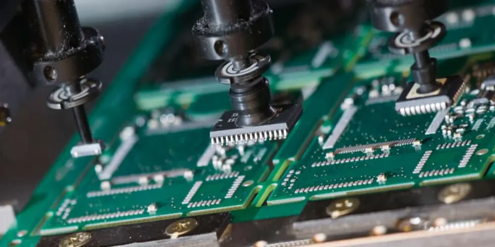
- Component Placement: All the components are placed into designated locations using a pick-and-place machine. This machine is an automated tool. According to pre-programming, the robot arm can pick up electronic components from a tray or reel and place them at the specified position on the circuit board. With the help of autonomic machines, it is highly saving manufacturing time and labor costs.
- Reflow Soldering: Circuit board is brought to the reflow oven with components already placed onto it. This process includes 4 key steps: pre-heating, soaking, reflow, and cooling. During the reflow step, the temperature will be at its peak (usually 220°C to 250°C based on the kind of solder paste used) to melt the solder paste. Then quickly cool down to solidify the solder joints at the cooling phase.
What Is THT?
THT (Through-hole technology) involves passing the leads of a component through pre-drilled holes in a PCB and then soldering the leads to pads on the back side. This technology is often used to assemble large components that need to withstand physical stress, and the leads and pads form a strong mechanical bond. Then, let’s go through the three key assembly processes of THT.
Three Key Steps of THT Assembly Process
Drill Holes: The PCB design file will define the location, diameter, and depth of each hole. While drilling, you must consider factors like hole size, alignment, and board material to be compatible with component leads and to prevent PCB damage. Then select the appropriate drilling machine to perform the drilling activities according to the design files.
Insert Components: Insert the THT component into the pre-drilled hole for subsequent soldering. Depending on the production volume and component’s complexity, insertion can be done automated for high-volume manufacturing or manually for low-volume or prototype builds.
Waving Soldering/Manual Soldering: After all the components are inserted on the circuit boards, they may be processed using the waving soldering system or manually soldered. Wave soldering is an automated process where the PCB is passed through a solder wave. The solid mechanical as well as electrical connections between all component leads and PCB pads were established simultaneously when cooled. Manual soldering is performed using a soldering iron for soldering individual component leads sequentially onto the pads.
SMT vs THT: Pros and Cons Explained
In this table, we compare the advantages and disadvantages of SMT vs THT in detail, and you will have a deeper understanding of these two assembly methods.
| Pros | Cons | |
| SMT | ▪ Compact Design: The circuit board can have components installed on both sides, which significantly reduces space. SMD components are usually much smaller than THT components. Manufacturers can fit more components on a smaller circuit board, achieving a more compact design. ▪ Faster Assembly Speed: Pick and place machines are capable of placing thousands of components per hour with greater accuracy and speed. Reflow soldering shortens the manufacturing cycle and simplifies the soldering process even further. ▪ Improved Electrical Performance: Due to their shorter leads, SMD components can reduce inductance and resistance. This improves signal integrity and electrical performance of high-frequency circuit boards. | ▪ Mechanical Stress Sensitivity: Components are soldered directly to the surface of the circuit board and are susceptible to mechanical stress caused by vibration, thermal expansion, and PCB bending. ▪ Repair and Testing Challenge: SMD components are small and fragile, and are densely arranged on the circuit board, making detection or repair more challenge. Defects are also difficult to detect through visual inspection, requiring advanced testing equipment. ▪ Higher Initial Setup Cost: Specialized equipment such as placement machines, reflow ovens, and automated inspection systems are costly, especially for small manufacturers. |
| THT | ▪ Robust Mechanical Connections: Since the component leads are inserted into the holes and then soldered, a strong mechanical connection is provided. This robust connection can effectively resist mechanical stress. ▪ Fast Prototyping and Manual Repairing: THT components have larger lead sizes and visible solder joints on the board, making them easy to manually assemble and repair. Engineers can quickly locate, remove, and replace components, allowing faster iteration and debugging of PCB prototypes. ▪ Superior Heat Dissipation: THT components have larger physical sizes and longer leads, which provide a larger surface area for heat transfer. | ▪ Slower Assembly Speed: THT requires additional drilling, manual component insertion, or manual soldering, resulting in slower production relative to SMT. ▪ Lower Component Density: Components are large and require drilling for installation, taking up more PCB space. ▪ Long Leads’ Impact on High-Frequency PCBs: The long leads of components can easily lead to increased inductance and capacitance in high-frequency circuits, causing high-frequency signal distortion. |
SMT vs THT: 10 Key Differences Revealed
Selecting the appropriate assembly technique during the PCB assembly process will greatly enhance both the process’s efficiency and the final product’s quality. SMT vs THT both have their unique characteristics. We compare SMT vs THT in ten aspects, highlighting their key differences.
| Aspect | Surface Mount Technology (SMT) | Through-Hole Technology (THT) |
| Method of Component Attachment | Soldered directly to the PCB surface. | Inserted through holes in the PCB. |
| Component Features | Small size with flat co-planar leads or tails. | Larger components with longer leads. |
| Component Density | Allows double-sided mounting , high-density layout. | Low component density, requires drilling, taking up more PCB space. |
| Component Price | Generally higher due to smaller components and precision manufacturing. | Typically lower, as components are larger and less expensive to produce. |
| Mechanical Strength | Susceptible to mechanical stress (vibration/thermal expansion/bending). | Provides stronger physical connections, offering better resistance to mechanical stress. |
| Thermal Management | The small size of components results in limited heat dissipation. | The components are large in size and have long pins, providing a larger heat dissipation area. |
| Cost considerations | The initial equipment investment is high, but the cost is lower when mass production is carried out. | The labor cost is significant, while the beginning cost is minimal. |
| Assembly Speed | Faster assembly process, making it ideal for large-scale production. | Slower assembly process, more suitable for small-batch or prototype production. |
| Repair | Specialized equipment such as X-ray inspection, is required to detect defects and repairs are difficult. | Solder joints are visible and easily repaired by hand. |
| Application | Best for lightweight, compact devices such as wearable devices. | Ideal for applications that need strong connections, high-temperature operation, or easy prototyping. |
Last Words
When choosing SMT vs THT, you should consider several key factors, such as electronic device characteristics, performance requirements (especially for high-frequency applications), production volume, and cost. Surface mount technology has high automated production efficiency and is suitable for large-scale production. For small batches or prototype production, through-hole technology might be more suitable. Understanding your project requirements and these two assembly methods will help you make the most appropriate choice.