A PCB resistor is a passive PCB component that can control or limit the current flow in the circuit. From fixed to variable, from surface mount to through-hole, and from linear to non-linear, circuit board resistors come in a variety to suit different circuit needs. This blog will detail different PCB resistor types and the crucial factors to take into account when selecting the ideal one. With this knowledge, making a well-informed decision like a pro is simple.
Different Types of PCB Resistors
Depending on whether the resistance value is adjustable, current-voltage relationship, and mounting style, PCB resistors are classified into three types: fixed and variable resistors, linear and non-linear resistors, and SMD and through-hole resistors.
Fixed and Variable Resistors
- Fixed Resistors
The resistance of the fixed resistor is constant. They can be built with materials like metal, carbon, ceramic, etc., and are found in many types. The 5 common fixed resistors are explained below in detail.
- Carbon Composition Resistors
Carbon composition resistors made of ceramic powder and carbon particles are the oldest resistors. They are economical and are 1/4 to 2 watts power-rated with a bad tolerance of ±10% due to temperature effect. Though commercially stable, carbon composition resistors are noisy and suffer from voltage coefficient issues. These PCB resistors are utilized for general applications where accuracy is not a prime factor.
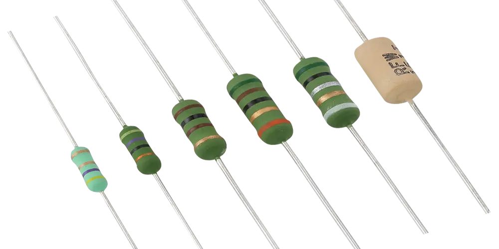
- Wire-Wound Resistors
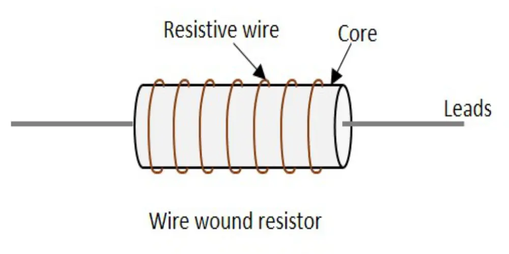
Wire-wound resistors are created by winding resistive wire (manganine or nichrome) around an insulating rod or core made of ceramic, glass, or plastic. These PCB resistors are suitable for high-power applications, can handle up to 100 watts or more, and typically have commercial tolerances of about ±5%. However, wire-wound resistors have a large inductance effect, they do not perform well in high-frequency circuits.
- Fusible Resistors
Fusible resistors are the same as standard fixed resistors under normal conditions. However, a fusible link is integrated that melts under excessive electric current and provides overload protection for the circuit. They are employed in power supply and distribution circuits and can be reset by manually replacing the fuse wire.
- Metal Film Resistors
A thin film of tin oxide or nickel chrome is deposited on a ceramic substrate to create metal film resistors, which provide improved stability and accuracy. High tolerance (±1%) and temperature stability are the primary attributes of these PCB resistors, and the power ratings range from 1/10 to 1 watt. They can withstand greater peak voltages and have a smaller voltage coefficient.
- Metal Oxide Film Resistors
Metal oxide film resistors use a metal oxide material such as tin oxide instead of a metal film. They are very accurate with tolerances down to ±0.5% and remain very stable over time and temperature. These PCB resistors offer noise suppression due to their low thermal EMF and are well-suited for high-frequency applications up to GHz. Metal oxide film resistors are also very reliable and can handle pulses very well. Due to these traits, they are often utilized in high-precision test equipment.
- Variable Resistors
Variable resistors, which can change the resistance value, are frequently used to regulate the circuit’s voltage and current levels. There are two main types: potentiometers and rheostats.
- Potentiometers
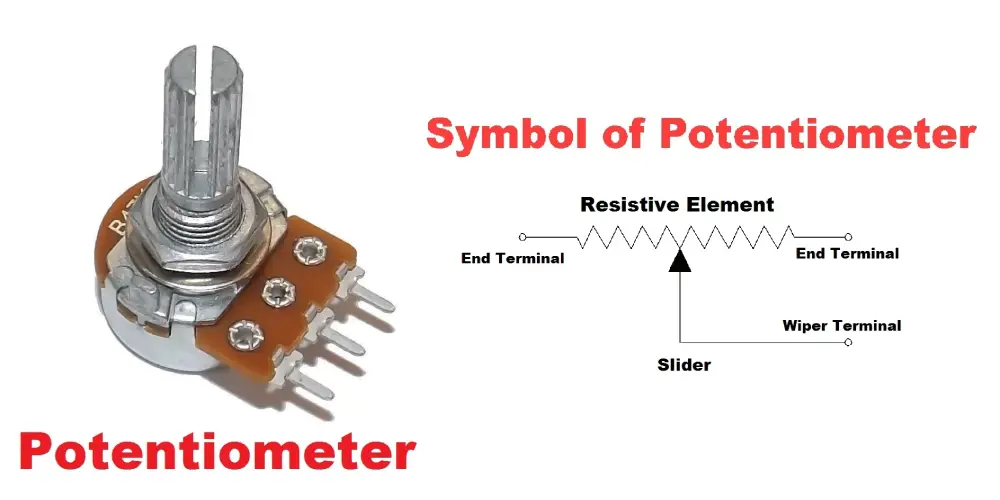
Potentiometers have three terminals, and the position of one of the terminals (wiper) is adjusted by rotating the knob. When the knob is rotated, the wiper moves relative to the fixed wire, changing the resistance voltage division ratio, thereby achieving voltage or signal adjustment. These PCB resistors are often used for volume control in audio systems because they can smoothly adjust the volume from low volume to high volume, or vice versa, and can also set specific circuit parameters.
- Rheostats
Variable resistors only have two terminals, one of which is connected to the circuit’s power source and the other to the ground. Unlike the working principle of potentiometers, there are no wires inside, and the current flowing through them is controlled by adjusting the sliding contacts.
Linear and Non-Linear Resistors
- Linear Resistors
As the applied voltage changes, linear resistors change their current value in exact linear proportion. These resistors always follow Ohm’s law and can be fixed or variable.
- Non-Linear Resistors
Non-linear resistors do not follow Ohm’s law, and the current varies in non-linear proportion to the applied voltage. This PCB resistor type can also be variable or fixed resistors and below are some frequently used non-linear resistors.
- Thermistors
Thermistors can be used to detect small temperature changes, and the resistance changes with temperature, causing a change in current. This PCB resistor is often used in vehicles, rechargeable batteries, thermometers, and consumer electronics.
- Varistors
Varistors are typically made of semiconductor materials, and the resistance varies with applied voltage. They can effectively suppress high transient voltages. As varistors have high resistance at low voltages, but their resistance drops significantly above a specified voltage. This property makes them ideal for use as surge protectors to prevent damage to sensitive electronic equipment.
- Light Dependent Resistors
Light dependent resistors are also called photoresistors. The resistance value depends on the intensity of light shining on it. In the dark, the resistance value is the highest, and as the amount of light increases, the resistance decreases. They are made of semiconductor materials such as cadmium sulfide or cadmium selenide.
SMD Resistors and Through-Hole Resistors
PCB resistors are divided into SMD and through-hole resistors based on the assembly method. The following are common types of circuit board resistors in each category.
- Through-Hole Resistors
- Axial Resistors
The leads of axial resistors are drawn from both ends of the resistor and set in a straight line. This PCB resistor is a simple structure with a low price and is suitable for spacious layout space.
- Radial Resistors
The leads of the radial resistors are removed from the same side in a common double-row pattern. It occupies less board space and is well-suited for compact and high-density layouts.
- Dual in-line Package (DIP) Resistor Networks
The through-line package resistor network contains a number of resistors in one package, with a dual-in-line package. It is compact and well-suited for those circuit designs that require multiple resistors, such as IC configurations.
- SMD Resistors
- Chip Resistors
Chip resistors are small rectangular resistors, which are directly soldered onto the PCB surface. They are low in cost and size and are being utilized to a great extent in high-density circuit design.
- Network Resistors
SMD resistor networks are the same as DIP networks but are surface mountable. They contain a number of resistors in a single package and are very handy to use in circuits that need more than one resistor, as they conserve space and simplify the installation.
How to Choose the Ideal PCB Resistor?
When choosing a PCB resistor, these seven factors should be considered, and let’s explore these factors one by one.
Resistance Value
First, analyze the circuit design or schematic and then use Ohm’s law calculations to determine the resistance value needed for the circuit. The resistance value specifies the amount of current allowed to pass through a certain section of the circuit and assists in determining the voltage level.
Power Rating
The power dissipated by the PCB resistor can be calculated by using the formula P = V²/R or P = I²R. It is advisable that the circuit board resistor should have a rating of twice the calculated power to prevent overheating and ensure reliability. In applications where the resistor is in poorly ventilated or high-temperature areas, a higher rating power will be required. Higher power resistors are generally larger, and the available space for PCB must be taken into account.
Tolerance
The tolerance is the highest acceptable difference between the nominal value and the working value of a resistor, normally represented as a percent value. It can be a 5% higher or 5% lower actual resistance when it’s for 5% tolerance. In high-accuracy circuits, the tolerance can be ±1% or higher accuracy, and average usage can take ±5% tolerance or ±10% tolerance depending on price considerations.
Temperature Coefficient
Temperature coefficient indicates how resistance changes with temperature. Selection of a resistor with a suitable temperature coefficient will keep resistance value to be stable over the actual operating temperature range and thus has no adverse impact on circuit operation. Low-temperature coefficient indicates a small change in resistance value with temperature and is most appropriate for high-precision circuits where stability is of the highest importance. Low-temperature coefficient resistors are, however, costly, and cost and performance have to be traded off.
Voltage Rating
The voltage rating is the maximum voltage a resistor can sustain, and it is a measure of the amount of current the resistor can carry without causing damage. It must be greater than the maximum voltage across the resistor with some margin of safety to prevent overloading.
Size
Evaluate the available space on the board. Small resistors are convenient for compact designs but have lower power handling capacity. Large resistors can handle more power while dissipating heat more efficiently. Secondly, consider the PCB assembly method, especially for manually soldering which is easier to handle with larger resistors.
Noise
Resistors generate noise when in operation and noise rises with the increase in frequency. In sensitive circuits, low-noise resistors should be selected.
Main Applications of Circuit Board Resistor
PCB resistors play many key roles in circuit boards, the following are their main applications.
Current Limiting
When a PCB resistor is connected in series with an LED, integrated circuit (IC), or other precision electronic component, its function is to limit the current that passes through those components, with the goal of preventing them from being damaged by excessive current.
Voltage Division
Voltage dividers are simple and practical circuits whose working principle is based on two or more resistors connected in series to a voltage source. With this arrangement, a lower controlled voltage output can be produced from a higher supply voltage. This circuit is widely used in power supply design, bias networks for transistor amplifiers, ADC interfaces, etc.
Pull Up/Down
Pull-up and pull-down resistors are connected between the logic output of the integrated circuit and the positive or negative power rail (ground). Their main function is to ensure that a known logic voltage level is maintained when the IC output is in a high-impedance state. This design provides a clear default state for the circuit, effectively preventing the occurrence of logic errors and false triggers, and is a key component to ensure the reliable operation of various digital logic circuits.
Biasing Networks
In transistor amplifiers and analog integrated circuits (op-amps), resistors are used to provide the proper direct current (DC) bias voltage or current levels to ensure that they operate properly in their linear region of operation.
Feedback Circuits
Resistors play a key role in the feedback loops of operational amplifiers (Op-Amp), digital-to-analog converters (DAC), analog-to-digital converters (ADC), etc. They are used to adjust gain, stability, frequency response, and output impedance to ensure that the circuit functions as intended.
Takeaway
Choosing the right PCB resistor for a circuit board can optimize its performance, reliability, and even cost. When choosing, it is important to consider the seven key PCB resistor parameters, which can then be aligned with the actual needs of the circuit to help make an informed choice. Contact UnityPCB’s expert team to get professional advice and solutions once you have any doubts throughout the selection process.