Rigid PCB is one of the most common types of PCBs in the electronics industry. It plays a critical role in many industries with its structural rigidity, reliability, and cost-effectiveness. This guide will explore the manufacturing process, types, advantages, and applications of rigid PCBs in depth. You will have a comprehensive understanding of it.
What Is Rigid PCB?
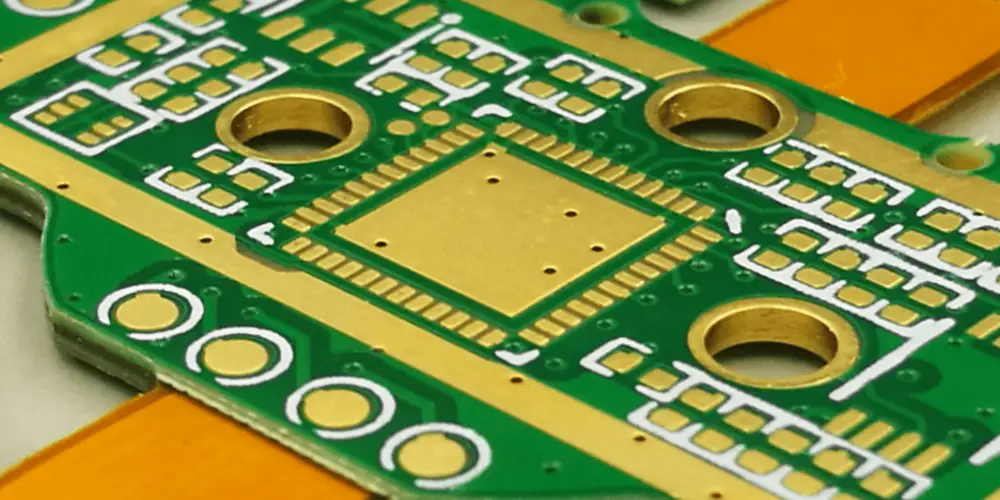
Rigid PCB is the most widely used type of printed circuit board, constructed from a solid, inflexible substrate. The core substrate is typically FR-4 known for its excellent hardness, thermal performance, and dielectric properties. Structurally, a rigid PCB consists of four key layers: substrate layer for mechanical support and insulation, copper layer for conductive trace, solder mask layer for protection, and silk screen layer for identification. Once fabricated, rigid PCBs can’t be changed or modified. These PCBs offer superior mechanical strength, structural stability, and resistance to deformation.
How to Fabricate Rigid PCB Board: Essential Manufacturing Steps
Here you will find a detailed explanation of the essential procedures of rigid PCB fabrication.
Designing the Schematic and PCB Layout
In rigid PCB design, designers can use PCB design software to assist in design. Create a schematic and convert it into a PCB layout.
Lamination Process
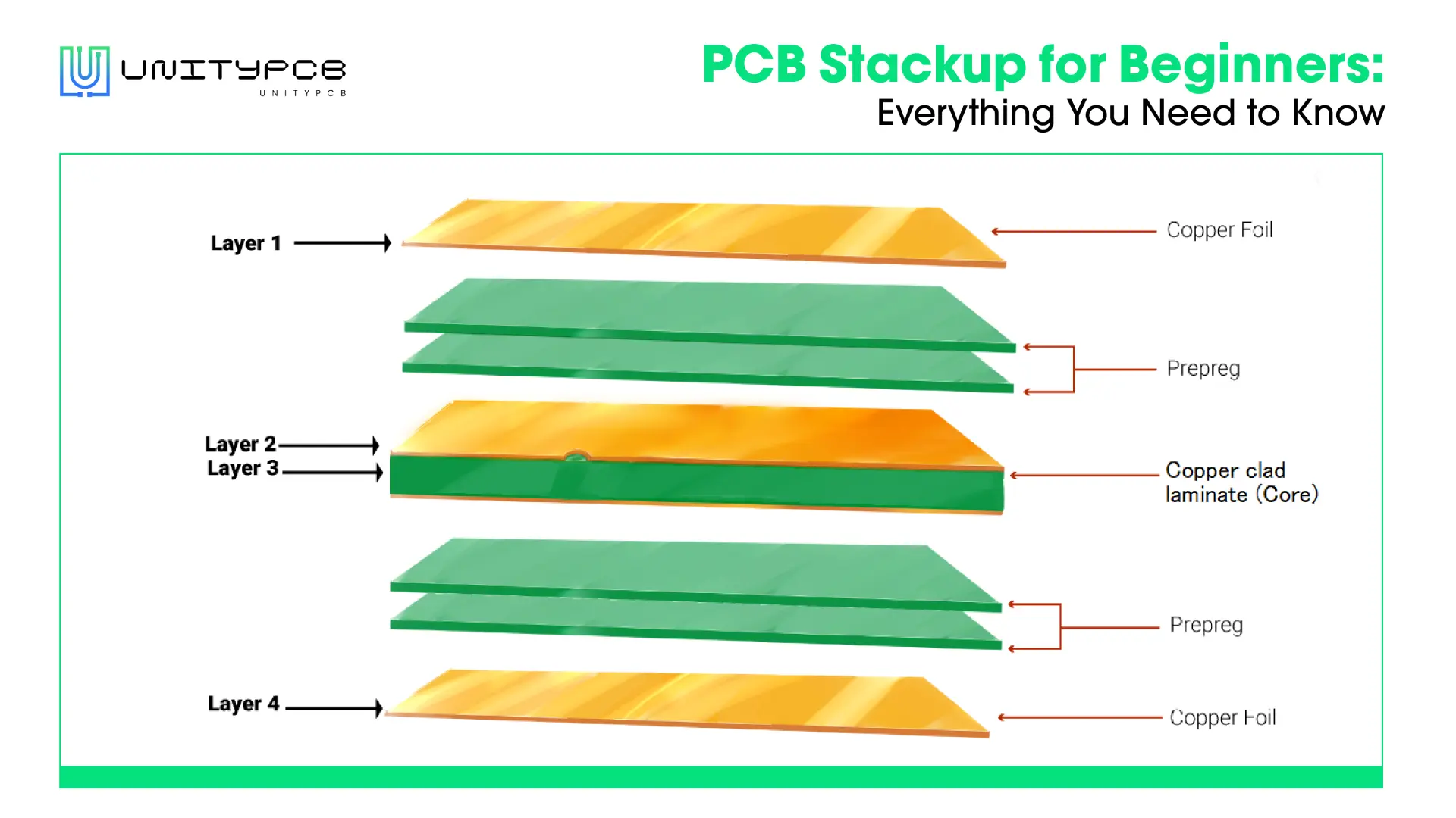
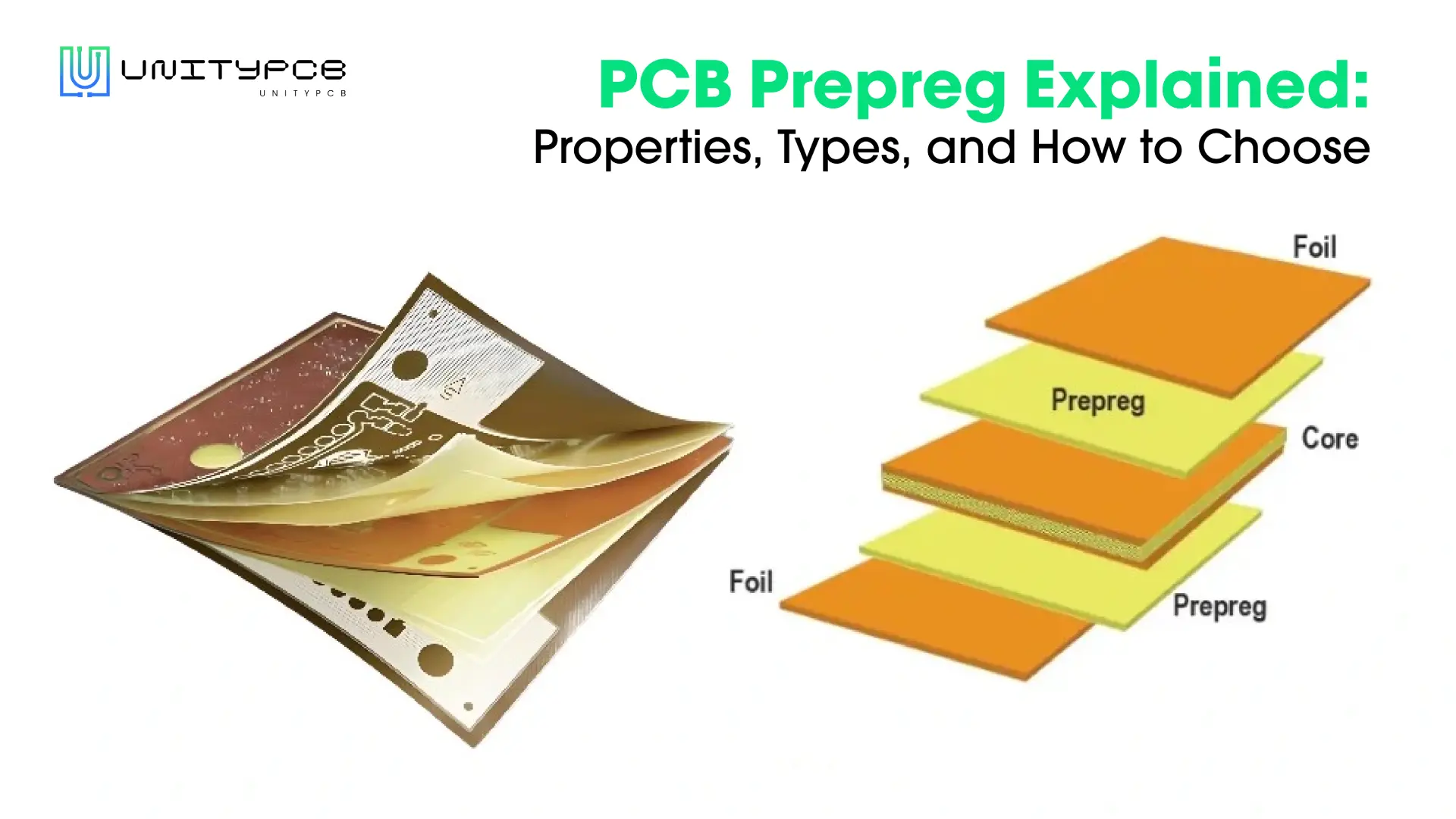
The PCB lamination process is performed in a heat press. The prepreg softens and then is tightly bonded to the copper foil laminate under high pressure.
Applying Photoresist
Photoresists are employed to protect the copper layer from chemical etching. Positive photoresists are the most common type. Their property is that parts exposed to ultraviolet (UV) light become easily soluble.
Etching Process
The etching process removes unwanted copper from the copper layer, leaving behind the required circuit pattern. The exposed copper areas are removed using chemical methods, while the areas covered by the photoresist remain protected. Then, the remaining photoresist is cleaned off, leaving only the desired tracing.
Drilling
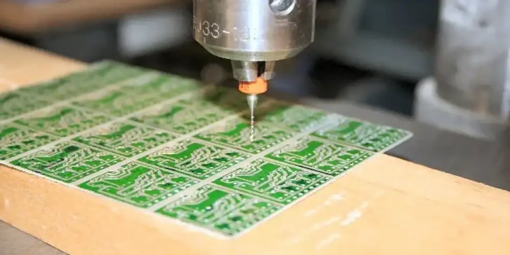
PCB drilling can be done with a computer-programmable drilling machine, which optimizes the drilling speed, pressure, and geometric parameters to ensure hole accuracy. Multiple boards can generally be stacked to improve production efficiency.
Solder Masking
The solder mask is usually applied to the copper layer of the rigid PCB to prevent unintended soldering and protect the copper conductive path from damage. Liquid photoimageable solder mask (LPSM) and epoxy liquid screen printing are two common methods of applying solder masks.
Surface Finish
PCB surface treatment applies a protective coating to exposed solderable areas, primarily to prevent copper oxidation, ensuring reliable solder joints and strong solderability. Common techniques include HASL, ENIG, and OSP.
Silkscreen
The screen print layer stays on the surface of the PCB solder mask layer, adding various identification information to the board. White is the most frequently used screen printing color but other colors of choice can also be used. There is a traditional method of transferring the ink pattern onto a rigid PCB using a stencil and a scraper. Liquid Photo Imaging (LPI) is more suitable for high-density rigid printed circuit boards.
Different Types of Rigid Circuit Boards
In this part, we have listed several common types of rigid PCBs. Different types of rigid printed circuit boards can adapt to various needs.
Single-layer PCBs
Single-layer PCBs have a single conductive copper layer, in which all components are assembled on the same side. These boards occupy a larger space in devices. Their simple design and fast manufacturing process make them ideal for low-density electronic applications.
Double-layer PCBs
Double-layer PCBs have conductive layers on both sides, allowing components to be mounted on either side. This enhances component placement options and spaces. They offer greater design flexibility and support more complex circuit designs than single-layer PCBs.
Multilayer PCBs
Multilayer PCB consists of 3 or more conductive layers that are laminated together under high temperature and pressure. Both sides of the PCB board can have components installed. Multilayer circuit boards reduce the need for interconnect wiring, save space, and are more compact in design.
Heavy Copper PCBs
Heavy copper PCB features significantly thicker copper layers compared to standard PCBs, enabling it to carry higher currents. The standard PCBs typically have a copper thickness of 1 ounce, heavy copper circuit boards range from 3 to 20 ounces or more. The increased copper thickness enhances current-carrying capacity, thermal performance, and durability.
High-Tg PCBs
High-Tg PCB refers to printed circuit boards made from substrate materials with a glass transition temperature (TG) above 170°C. High-Tg circuit boards can withstand higher heat loads during soldering and high-temperature operations. It is an ideal solution for high-temperature applications, due to excellent thermal performance.
High-Frequency PCBs
High-frequency PCB refers to a printed circuit board designed for processing high-frequency signals, typically used in radio frequency (RF) and microwave applications. High-frequency circuit boards use materials with a low DK (dielectric constant) and low DF (loss factor), which help reduce signal attenuation and distortion. Common substrate materials include PTFE and ceramic materials, which provide excellent signal transmission performance and stability.
Metal Core PCBs
Metal core PCBs are circuit boards with substrates made of aluminum or copper, which enhance thermal conductivity and effectively transfer heat from critical components to less critical areas. Metal core circuit boards are popularly used in high-power LED lighting.
Key Benefits of Rigid PCBs
Below, we outline some major benefits that make rigid PCB a popular choice for a wide range of applications.
Budget-Friendly Solution
Rigid PCB manufacturing technology is well-established, enabling efficient large-scale production with high quality. Compared to flexible PCB and rigid-flex PCB, rigid PCB offers a more cost-effective solution, making them the ideal choice for projects with a limited budget.
Higher Functionality
Rigid PCB supports multi-layer design, which provides higher functionality and design flexibility for circuit boards. As circuit integration increases, rigid circuit boards enable high-density circuit designs, satisfying the needs for miniaturization and high performance in various devices.
Low Electronic Noise
Rigid PCB can reduce electronic noise and improve signal integrity through optimized layout design. This is critical in devices with high precision and high stability requirements.
Resilience to Mechanical Stress
Rigid PCB substrates have good vibration resistance and can effectively protect components on the circuit board from external impact. Its solid structure ensures that it is not easily damaged during manufacturing, assembly and use, and has excellent resistance to mechanical stress.
Simplified Maintenance and Repair
Maintaining and repairing the rigid PCB design is easy. Its components are clearly marked and the traces are easy to identify, which helps maintenance personnel quickly locate and repair problems.
Where Are Rigid Printed Circuit Boards Typically Used?
Consumer Electronics: Rigid PCBs are extensively utilized in a variety of consumer devices that are integral to our daily lives.
- Computer
- Smartphones
- Televisions
Medical: Rigid PCBs are mainly applied in large, non-portable equipment that requires high reliability and stability in medical applications.
- Tomography equipment
- Electromyography (EMG) machines
- Magnetic Resonance Imaging (MRI) systems
Aerospace: Rigid PCBs used in aerospace need to adapt to extreme environmental conditions. It is usually applied for copper or aluminum substrates, which have better thermal conductivity.
- Auxiliary Power Units (APUs)
- Airplane cockpit instrumentation
- Power converters
Automotive: Rigid PCBs play an important role in the stable operation and reliability of vehicle systems.
- Engine control units
- Infotainment systems
- Safety modules
Industrial Equipment: Rigid PCBs need to withstand harsh operating conditions and vibration resistance in industrial devices.
- Power supplies
- Motor controllers
- Pick and place equipment
Rigid PCB vs. Flex PCB: Major Differences and Comparisons
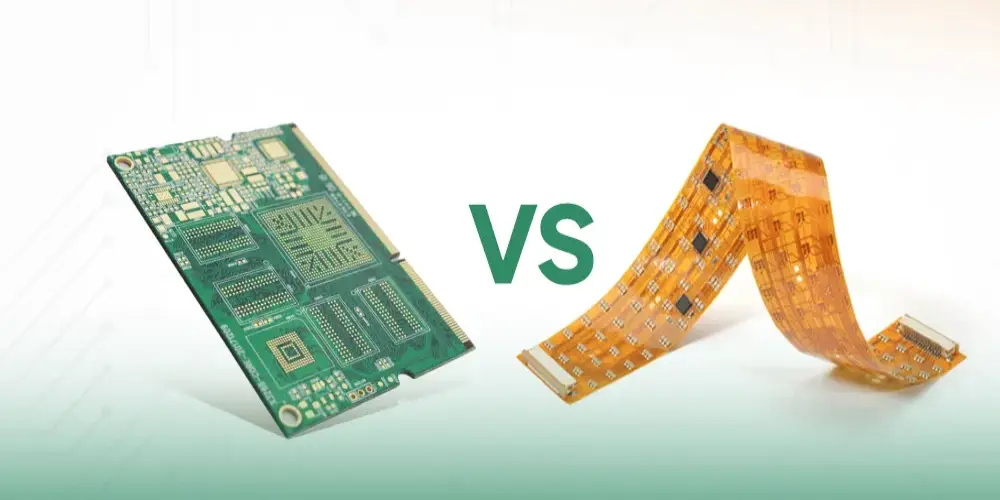
| Parameters | Rigid PCB | Flex PCB |
| Flexibility | Inflexible, rigid structure | Flexible, can bend and twist |
| Materials | Commonly made with FR4, fiberglass, epoxy resin | Made with flexible materials like polyimide |
| Space Efficiency | Less efficient, requires more space | More efficient, allows for compact designs |
| Design Complexity | Simpler to design and manufacture | More complex design due to flexibility requirements |
| Manufacturing Cost | Typically cheaper to produce | Generally more expensive due to material and manufacturing complexity |
| Size | Fixed, usually larger | Flexible, can adapt to confined or irregular spaces. |
Rigid PCB is typically low-cost and easy to manufacture, suitable for devices where space is relatively sufficient. Flexible PCB offers superior space efficiency and flexibility for compact applications. Nevertheless, its design complexity and production cost are higher.
Ending Notes
Rigid PCB is indispensable in many electronic devices. Understanding its basics will allow you to make a wise choice when choosing the right circuit board for your project. Moreover, if you’re seeking an expert partner for rigid PCB manufacturing, UnityPCB is an excellent choice. With nearly 20 years of PCB manufacturing experience, UnityPCB offers reliable and innovative solutions to global clients, ensuring high-quality performance and exceptional service. Just contact us to quote now, and will reply to you promptly.
